![]()
When an object moves through a fluid (either liquid or gaseous), it disturbs the the fluid, forcing it to make room for passage of the object. (Such motion is relative so we can think of either the object or fluid doing the moving. But for simplicity of language we will use the vocabulary describing the object to be moving. Still all the following will be equally true for a fluid such as a river flowing past a fixed object.) The disturbance can result in both smooth flow and turbulence (e.g. white water). Below we will consider first the situation where the object is submerged in the fluid such as an aircraft flying through the air. And then we will consider objects on a fluid's surface such as a moving boat.
The particles of the fluid must move out of the way of the moving object. The moving object creates a compression wave in front of its motion. In a gaseous fluid such as air, this compression wave moves roughly at the speed of the particles in the fluid, essentially the speed of sound which shares the same mechanism. In the process of getting out of the object's way, the particles in front may slightly increase their own speed using energy transferred from the approaching object. (The process may be compared with the bell on a streetcar warning those ahead to disperse.) In a fluid not easily compressed, such as water, friction prevails so that this bow wave does not precede the object very far. This wave of disturbance, which in the end deflects the fluid to either side of the passing object, is most efficiently produced by a blunt, flat surface tangent to the path of motion. So the most efficient shape for the leading surface of a moving object is nearly spherical.
If the object's speed through the fluid is greater than that of the speed of the fluid's particles, the compression wave cannot precede the body, allowing the fluid to move out of the path at the particles' own speed. Instead the fluid builds up intense pressure immediately in front of the object requiring the particles of the fluid to be forced directly to the sides by the passing object. The most efficient shape for the front of such an object is a narrow, pointed wedge shape optimizing the deflecting force to the side while minimizing the here useless forward force. This compression to the side builds up a pronounced shock wave such as the familiar sonic boom created by supersonic aircraft or a snapped bull whip. (This process might be compared to the snowplow on the front of a train, forcing the snow to either side. This requires much larger energy than that of a warning bell.)
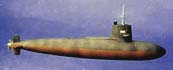 In addition, the spread of the fluid as the cross section of the object increases followed by the converging of the fluid as the cross section decreases following the object's passage results in an additional wave with the speed of the object but a wavelength determined by the property of the fluid and the object's length. In general this creates a series of regular trailing waves of diminishing intensity trailing behind the object and spreading to the side. The creation of turbulent flow greatly increases the energy required to move the object. Thus energy efficiency requires both minimum cross section and smooth flow. The most efficient shape for the balance of the object is tear shaped with its body gradually narrowing to a pointed trailing end. Note this is the general shape of dirigibles, submarines, and subsonic aircraft (although many have fuselages modified to produce some lift).
Consider a naval ship with its superstructure flowing through the air and its hull, supported by buoyancy, flowing through the water. The ship's motion disturbs the interface surface between the water and air. Generally the ship's velocity produces much less air resistance compared to that of the water. While the superstructure may also be streamlined to reduce air friction, the water's friction is also always far greater and therefore of more interest. The disturbances of the ship through the water cause pressures which distort the water-air surface into the V shaped bow wave and a gently curved trailing wake.
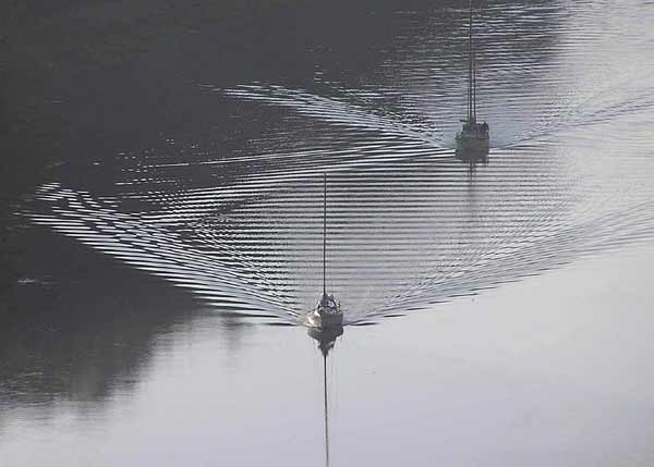
The bow pressure precedes the ship and disperses water to the side. This pressure forms a series of waves which disperse to either side of the ship in a V shape. The sharpness of the V depends on the vessel speed compared to the speed of the water waves. The increased pressure typically throws water up the bow of the ship which may deflect the water turbulently off to either side forming smaller, slower speed bow waves. These waves trail away in one or more often narrower V shapes to either side of the vessel. Behind the bow waves is a region of lower pressure. This is often noticeable along the side of the ship by the lower surface level. If the vessel is long enough and the speed slow enough, multiple wavelengths may be visible as the water surface meets the side of the ship. As speed is increased, a maximum hull speed is reached when there is just one wavelength matching the vessel length so that the vessel floats depressed in the wave trough it has created. This hull depression creates a wave train which trails behind the vessel. The wakes travel at different speeds and initial directions so that often the trailing wave extends faster to the side resulting in a series of bow waves superimposing on top of the trailing waves as in the photo below.
At higher speeds the wake is actually simplified. The relationship between the wake and the design of a ship's hull was quantified in 1877 by William Froude (b 1810, d1879), who used a series of scale model hulls to measure the resistance each when towed at a given speed. It was extended by Lord Kelvin in 1887 and Havelock in 1908. Froude's measurements led him to derive several formulae:
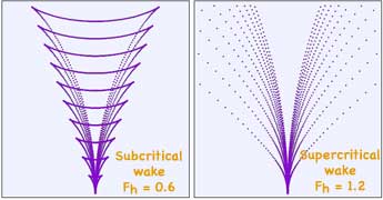
where V is the vessel's velocity and c is the speed waves propagate in the medium (e.g., water). This Froude number, Fr , is analogous to the Mach number relating an objects velocity compared to the speed of sound waves through the medium. (Note in computer generated wave predictions below, that at high speed, Fr = 1.2, some of the waves visible from the sailboats and predicted for low speeds have vanished.) Wave heights increase considerably as Fr → 1 and wave periods increase gradually as the ship’s speed does so.
When a ship operates in shallow water of depth H, the depth Froude number
compares the ratio of the ship’s speed, V, compared to the maximum wave speed in a given water depth, H (the g is the gravitational constant). Shallow-water effects become important when the wavelength is approximately twice as long as the water depth. As Fnh → 1, the wakes roughly converge to a single wake. The ship's motion is classified as sub-critical when Fnh 1, critical when Fnh = 1 and super-critical when Fnh > 1. Close to the critical speed the wave induced drag and consequently the wave height increases dramatically and most ships do not have a sufficient power to weight ratio to break through into the super-critical region. However some vessels with relatively light displacement and slender hull forms in either mono-hull or multi-hull format, can easily exceed the critical speed.
At the critical Froude number of 1, the velocity of the ship and the velocity of the waves are equal to √gH. The energy does not disperse back along the wave train behind the ship. Consequently a significant proportion of the propulsion is converted into wave energy in a tight V shape. When the ship has reached this critical speed, energy being pumped continually into the wake results in the wave height quickly increasing. Again, this is equivalent to a sonic boom created when an object achieves a speed equal that of sound waves through air.
Generally the shape of a hull is designed for a single optimum speed. As mentioned above the maximum hull speed is attained when a ship creates the trailing wake just equal the length of the hull at the waterline. At this speed the boat floats in the single first wave trough. The energy necessary to maintain that trough of water is essentially the energy of creating the series of trailing waves of that wavelength and magnitude. The Speed/length ratio was originally defined by Froude in his Law of Comparison in 1868 as:
To achieve faster speed requires a greater ship length compared to cross section, to match the wavelength of the maximum hull speed.
An alternate method of increasing efficiency is to divide the hull into several parallel sections such as a catamaran, then attempt to design each hull to minimize outward wake, and to try to cancel the inward wake of one hull with that from the other. More of this will be discussed in Expt. VII-4.
Another way to minimize wake is to lift the vessel out of the water to plane across the water surface or on wing-like hydrofoils. While those approaches have potential for minimizing wake, both have high energy requirements to lift the vessel.
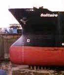
Placing a bulbous projection beyond the normal bow location has both speed and efficiency advantages. Presumably by moving the initial pressure wave further in front of the ship, the hull speed is increased by the increased wavelength. In addition, the pressure waves created by the projecting bulbous bow may partially cancel the pressure waves created by the remainder of the hull. This has been claimed to typically reduce energy consumption 5% (but in some cases as much as 25%) as long as vessel speed closely matches the optimum design.
Perhaps one of the more difficult aspects of ship design is understanding why a bulbous bow should be more energy efficient than a needle-nosed wedge design. Consider that the primary requirement is to move the water aside to permit passage of the vessel's largest cross section. So the issue is what bow design moves the water with the most efficiency and least expenditure of energy. One might still think a sharp wedge design which optimizes flow to the sides would always be superior to a design which bluntly exerts pressure directly ahead on the water.
You might try considering an approach of considering multiple samples of water and how each design provides for moving it aside the needed amount.
Or consider moving a fire engine down a crowded street expending the least amount of energy. Compare the following: Place a wedge shaped cow catcher on the front of the fire engine so that silently traveling down the street, obstructing people, animals and vehicles can be swept to the sides. Alternatively consider placing a loud siren on the front of the fire engine to warn people to clear a path for the fire engine. Consider which will likely result in the fire engine moving down the street the fastest with the least amount of effort.
When a liquid moving at high velocity slows to a lower velocity, an sharp rise may occur in the liquid surface, called a hydraulic jump. The slowing liquid piles up on top of itself (note center of photo of Saint Anthony Falls, Minneapolis) , converting some of the flow's initial kinetic energy to an increase in potential energy, with a part of the energy irreversibly changed through turbulence to heat. This is similar to how a shockwave forms at the bow wave of a boat, aircraft or other moving object.
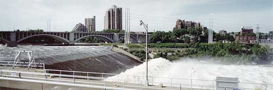
This phenomenon is dependent upon the initial speed of the fluid. If the initial speed of the fluid is below a critical speed, then no jump is possible. For initial flow speeds not significantly above the critical speed, the transition appears as an undulating wave. At higher speeds, the transition is more abrupt, and with enough enough speed, the transition front curls back upon itself creating violent turbulence and air entrainment. Hydraulic jumps designed by engineers can dissipate 60-70% of the energy, limiting damage to structures and the stream bed below spillways and dam outlets.
In a tidal bore, a rising tide creates a surge or wall of water moving up a river against water flowing downstream.
 Richard Feynman once described turbulence as
 the most important unsolved problem of classical physics.
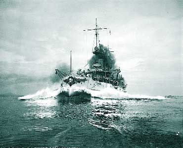
So this might provide an interesting subject to investigate further. One notes that as in this photo of a speed trail of the historic battleship USS Connecticut, bow waves, like the shock wave of hydraulic jumps and tidal bores, often have a significant amount of turbulence. And as noted above, this can dissipate a significant amount of energy. If we wish to harmlessly dissipate wake energy which can be destructive to beach structures and shorelines, there might be some value in further understanding such turbulence.
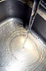 At right, as a faucet pours water into a sink, after the water initially impacts the surface there is smooth laminar flow. That jumps in a circular edge where the depth of the water suddenly increases and becomes turbulent.
![]()
to next experiment
to ie-Physics menu
to site menu