![]()
Visible light is the range of electromagnetic waves which can be seen by human beings. Those wavelengths range from 3.8 x 10⁻⁷ to 7.5 x 10⁻⁷ meters. The shortest visible wavelength is the color violet. The spectrum of colors range continuously through what we call indigo, blue, green, yellow, orange, and red. Ranges of electromagnetic radiation with wavelength longer than red are known as infrared and shorter than violet are known as ultraviolet. These wavelengths are just a small segment of the entire electromagnetic spectrum.
The behavior of light sometimes suggests that it is composed of particles and sometimes it is considered to be carried as waves. The modern electromagnetic theory of light considers light as particles called photons, which display all of the attributes and characteristics of waves.
The speed of light (c) in a vacuum is the absolute maximum speed of anything in the universe. The maximum speed of light, that through a vacuum, is 3 x 10⁸ m/s. The speed of light was first determined by the astronomical observations of Ole Roemer in 1674. The modern and accepted accurate value was determined by an experiment performed by Albert Michelson in 1926 using a rotating mirror and a beam splitter. The speed of light is one of the most important constants in modern physics.
Objects can be visually perceived when light from them reaches a human eye. Luminous objects produce light and as a result can be seen. stars and light bulbs are examples of luminous objects. Illuminated objects reflect light and are seen by the light, which comes from their surfaces, by reflection. Surfaces, which scatter the light, are producing diffuse reflection. Surfaces (such as mirrors) which reflect light in an organized way display specular reflection.
The intensity, I, of a light source is measured in units called candela (cd)
The rate at which light energy is produced by a luminous source is the luminous flux, Φ. Luminous flux is measured in a unit called the lumen. Φ = 4 π I
The density of light falling on a surface is called illuminance, E. This is a more useful measure of the amount of light. Illuminance is measured in lumens/m2, more often called lux. The formula for determining illuminance (or illumination of a surface) is: E = Φ / 4 π d2, or E = I / d2 where Φ is the luminous flux measured in lumens, I is the intensity in cd, and d is the distance from the surface to the source measured in meters.
The regular (specular) reflection of light rays from surfaces (usually mirrors) is a useful tool in the production of optical devices.
The law of reflection governs the behavior of reflected rays from regular (smooth) surfaces. The law of reflection states that the angle of incidence (incoming light ray) is equal to the angle of reflection (reflected light ray). The angles are measured from a normal line (perpendicular) drawn to the surface at the point of reflection.
Mirrors are optical devices, which use reflection to manipulate light. Plane mirrors have flat surfaces. Curved mirrors have surfaces, which are curved, for the purpose of reflecting light for some advantage. Curved mirrors are most often spherical or parabolic. Concave curved mirrors reflect light from the inside of the curved surface and convex mirrors reflect light from the outside of the curved surface.
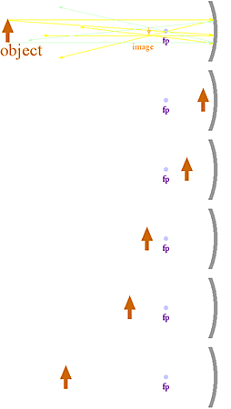
Images are produced by the intersection of reflected light rays which originating from an object. Light rays which converge from a concaved mirror intersect in front of the mirror and form a real image. If the reflected rays diverge in front of a convex, flat, or sometimes a concaved mirror, the mind imagines where it appears they came from, a virtual source. The intersection of these extended rays produce an image, constructed by the mind, which appears behind the mirror, a physical impossibility, is called a virtual image. Real or virtual are terms used to describe the character of the image. If the image is in the same orientation as the object (right side up) it is called an erect image. If the image is upside down it is called an inverted image. Erect and inverted are terms, which describe the attitude of the image. If the image appears smaller than the original object it is reduced and if it appears bigger than the original object it is enlarged.
Refraction is the bending of light rays as they pass from one medium to another at an oblique angle. The two media must have different optical density (i.e., the speed of light is different in each medium).
Light rays bend toward the normal when passing from less dense materials (having the faster light speed) to more dense materials (where light travels slower). The opposite occurs when the light moves from more optically dense to less optically dense media.
The ratio of the speed of light in a vacuum to the speed of light in a substance is called the absolute index of refraction, n, for that substance. n = 3.00 x 10⁸m/s / speed in the substance). (n for every real substance is greater than 1.)
| Medium | n | Medium | n |
| Vacuum | 1.0000 | Crown glass | 1.520 |
| Air | 1.0003 | Quartz | 1.540 |
| Water | 1.330 | Flint glass | 1.610 |
| Ethanol | 1.360 | Diamond | 2.420 |
Snell's Law of Refraction states that a ray of light bends in such a way that the ratio of the sine of the angle of incidence to the sine of the angle of refraction is a constant. Snell's law gives another definition of the index of refraction: n = (sin θi) / (sin θr). This gives the relative index of refraction. If the incident medium is a vacuum (air is close), the relative index is equal to the absolute index. Another form of Snell’s law: n1 sin θ1 = n2 sin θ2.
When light passes from a material, which has an absolute index of refraction higher than the material into which it is passing, the angle of refraction is greater than the angle of incidence. When the angle of refraction equals 90°, the incidence critical angle is reached. The critical angle does not allow any light to pass through the interface between the media because the refracted ray is parallel to the boundary. Exceeding the critical angle causes the light to undergo total internal reflection. This property of total internal reflection is used in light pipes and fiber communication bundles to keep all light inside (except at the ends) despite the material having gradual bends.
Lenses are curved objects made of a transparent material, which are cleverly designed to take advantage of refraction to bend the path of light in a controlled manner. Lenses, which are thicker in the middle than at the edge, are called convex or converging lenses. Lenses, which are thinner in the middle than at the edge, are called concave or diverging lenses. Images formed by convex lenses are similar to images formed by concave mirrors. Multiple lenses are assembled in appropriate combinations by clever engineers to produce optical devices such as microscopes, telescopes, binoculars and other devices to aid our sight.
When light passes through slits, which are very narrow, or through two or more slits, which are close to each other, they display diffraction. Diffraction is the spreading out of the light waves after passing through a narrow opening in a barrier or the edge of a barrier. When light passes through narrow slits, a pattern of light and dark lines appears due to interference between the diffracted waves. The dark lines are due to complete destructive interference of the light waves and are called nodes. The illuminated parts of the diffraction pattern are due to constructive interference and are called antinodes.
Single slit diffraction: When light passes through a single slit, bands of light and dark appear. In the following equation, x is the distance between the center of the first illuminated band and the adjacent dark band, λ is the wavelength of the light, w is the slit width and l is the distance from the slit to the screen (all measure in m or any uniform length unit):
x = l λ / w
Double slit diffraction: When light passes through a pair of small slits close together, a series of light bands flank the sides of the center illuminated band. In the following equation, x is the distance between the central band and the adjacent first order band, d is the separation between the slits, λ is the wavelength of the light, and l is the distance from the slit to the screen (all measure in m or any uniform length unit):
x = l λ / d
When white light passes through a diffraction array, each color is deflected a different amount producing a continuous spectrum of color. When monochromatic (only one color) light passes through a diffraction array, a pattern of nodes and antinodes will appear in this single color. The equation above for double slits is also valid for diffraction gratings, except that d represents the slit spacing (m).
 |
Ray optics is an exercise in Euclidian geometry (Euclid of Alexandria, Egypt, f300BC), adopted for understanding the paths of light rays. It assumes that light travels in straight lines unless its path is changed by reflection or refraction. Light rays approaching from different directions reflect of a curved mirror in a wide range of directions. However by selectively choosing several well located light rays, the behavior of the mirror can be understood and the paths of a large number of other light rays determined.
|
| object | image | |||
| location | character | location | attitude | size |
| Infinity | ||||
| beyond center of curvature | ||||
| at center of curvature | ||||
| between center of curvature & focus |
||||
| at focus | ||||
| between focus & mirror | ||||
real – formed by light rays which intersect in space in front of the mirror.location:
virtual – formed by light rays which intersect when traced back behind the mirror.
the actual location of the imageattitude:
inverted – upside downsize:
erect – right side up
enlarged – larger than the object
reduced – smaller than the object
same size
 |
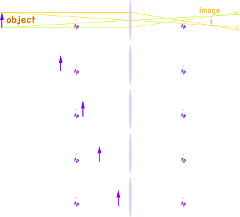
Ray optics can be used to approximated the paths of light passing through thin lenses using rules similar to those used to understand curved mirrors. Generally light rays refract passing through both surfaces of a curved lens. By selectively choosing several well located light rays, the effect of the lens on the path of light can be understood.
|
| object | image | |||
| location | character | location | attitude | size |
| Infinity | ||||
| Beyond twice focal length | ||||
| At twice focal length | ||||
| Between focal length & twice focal length | ||||
| At focal length | ||||
| Between focal length& lens | ||||
real – formed by light rays which intersect in space opposite lens from object.location:
virtual – formed by light rays which intersect when traced back to object's side of lens.
the actual location of the imageattitude:
inverted – upside downsize:
erect – right side up
enlarged – larger than the object
reduced – smaller than the object
same size
![]()
to next experiment
to e-Physics menu
to site menu