Click on any photograph to view larger image.
Click on any photograph to view larger image.
| QuarkNET team at the Stanford Linear Accelerator Center | 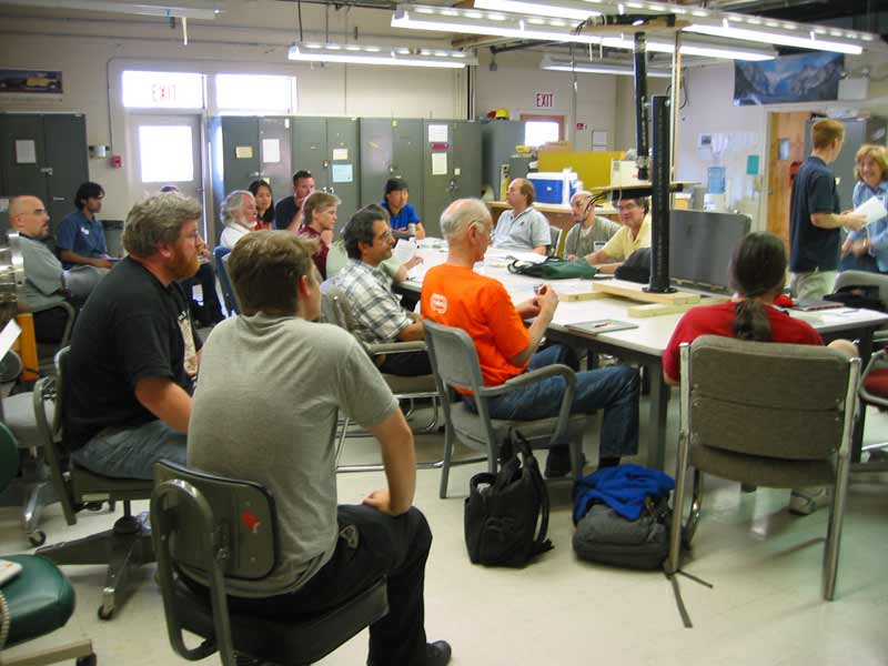 |
 |
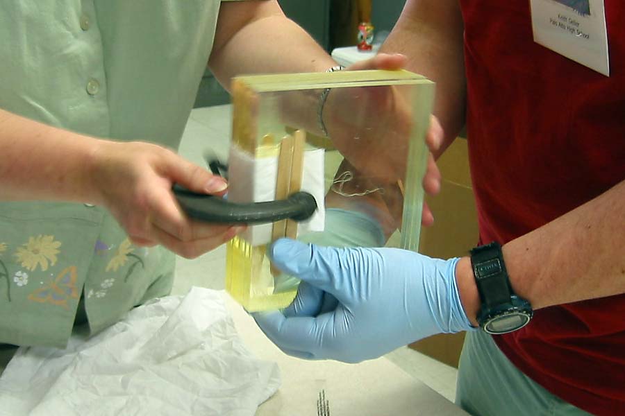
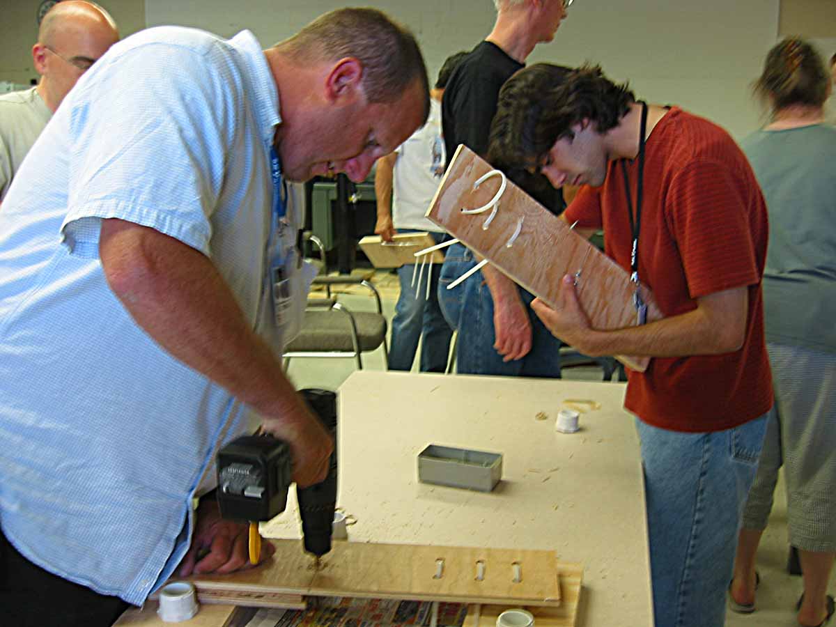
Layers of plastic parts are lightly clamped together to avoid rounding edges during sanding. A few small pieces of double sided tape are placed between the layers to prevent parts from moving independently and to protect surfaces. It was found that too much tape makes it difficult to separate the layers when done. The faces are protected from scratches from the metal clamp faces. Gloves are worn to protect the plastic from skin oils. Thomas Glanzman, answers questions. |
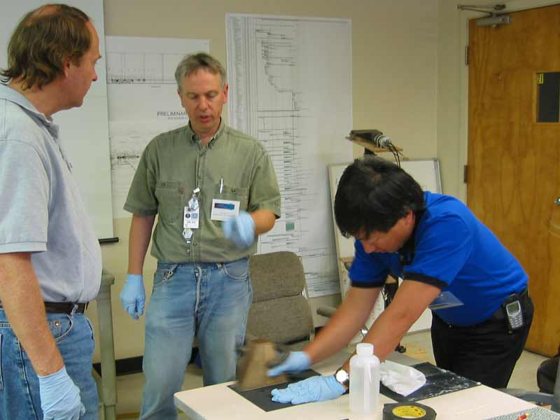
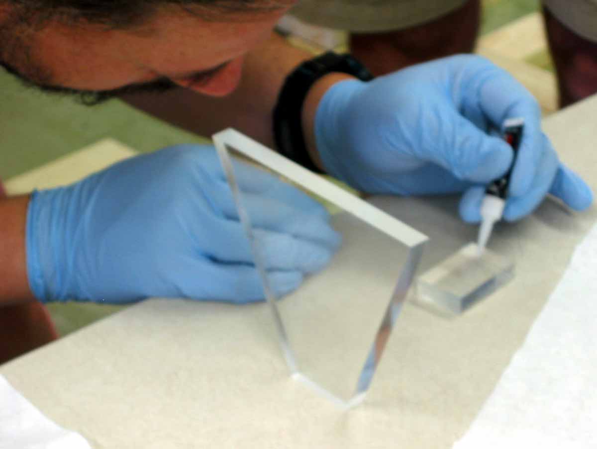
| The edges where light will be transmitted to adjacent parts need to be smoothed with successive 60 to 600 grit wet/dry silicon carbide sandpaper to remove scratches and prepare for gluing. | 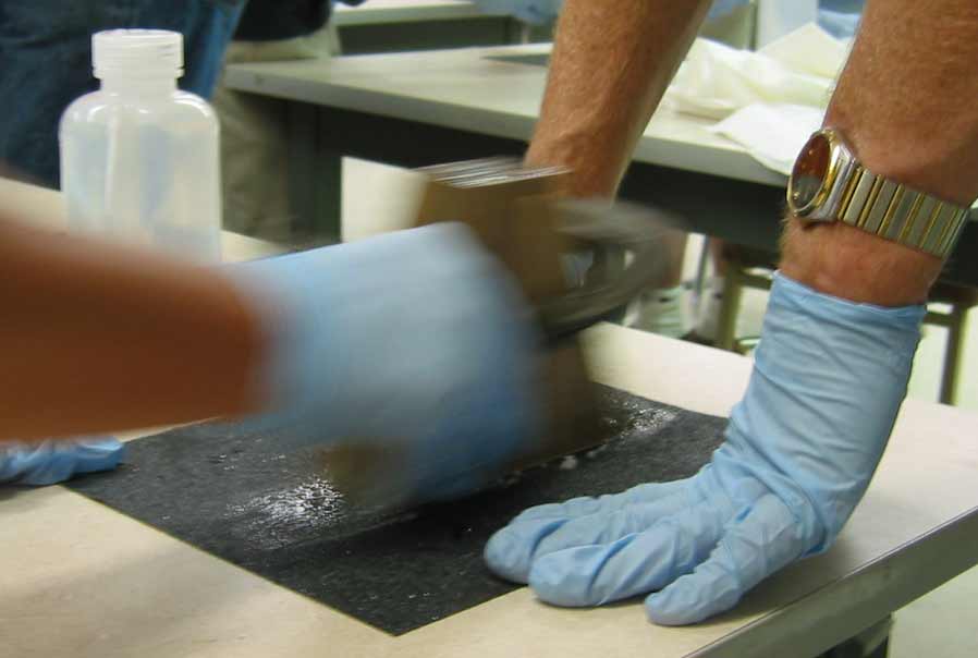 |
| Properly smoothed surfaces have a luster and no noticeable remaining scratches. |  |
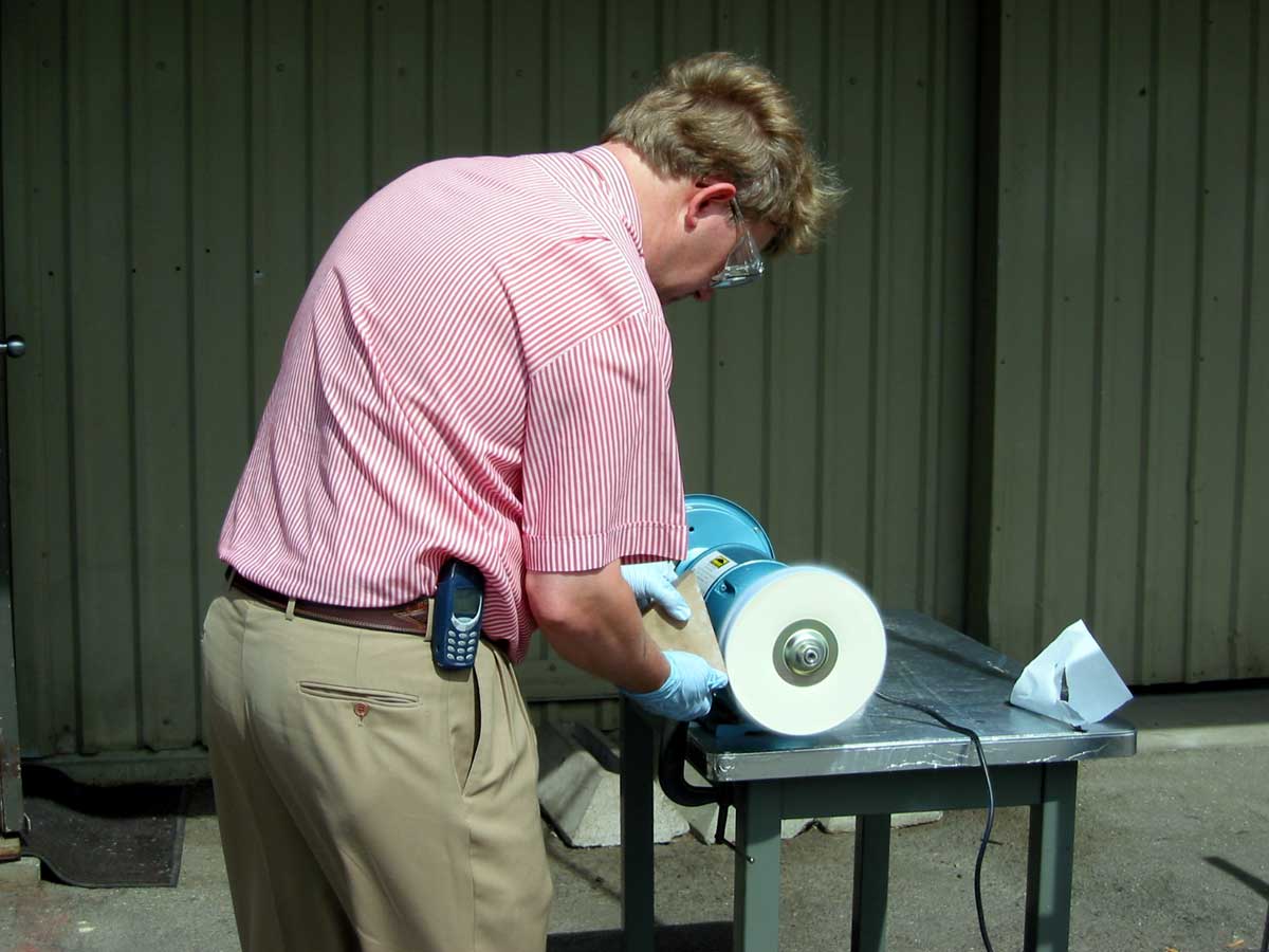 |
The sides of the light guides need to be further polished to reflect light into the photomultiplier tubes. The lucite light guides can withstand the heat generated by an electric polishing wheel, while the more delicate scintillator plastic is polished by hand. |
| The shined surface reflects light like a sheet of glass. |  |
 |
The scintillator blocks also need to be smoothed. The outside edges need to be sanded to 1500 grit and polished to reflect light towards the photomultiplier tube. The edge to be attached to the light guide needs to be finished to 600 grit to allow a surface for glue adhesion. The glue will provide a medium for light transmission of about the same index of refraction so that surface needs not be polished. |
| Preparing Cerium Oxide polish on mole skin. | 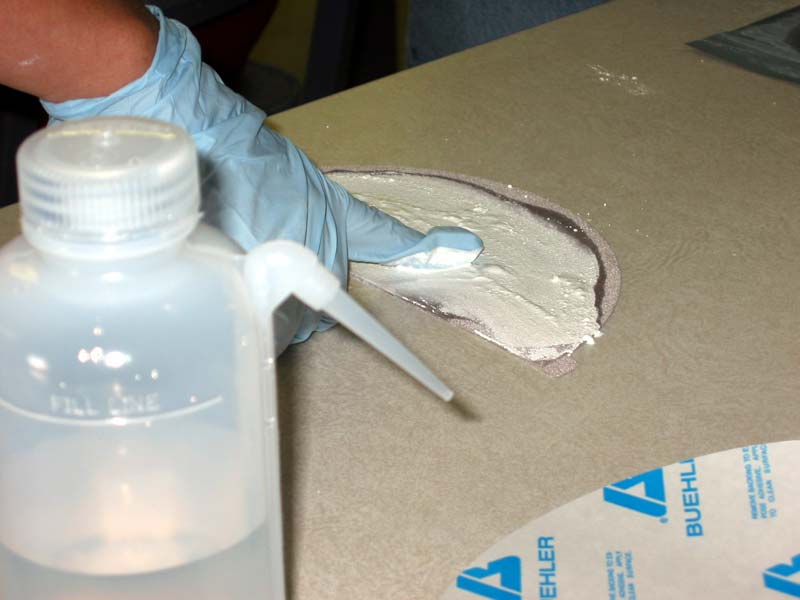 |
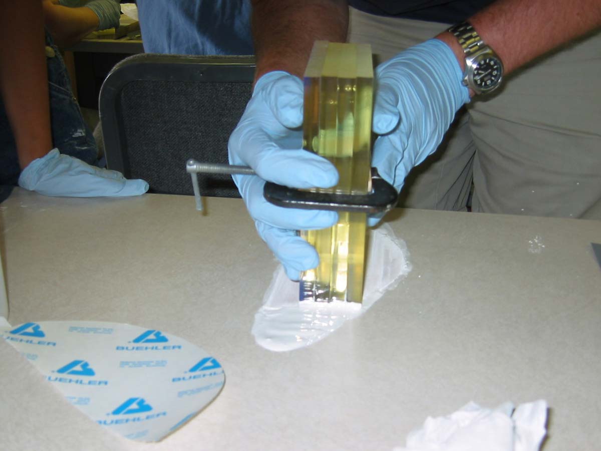 |
Carefully polishing a set of scintillator blocks. |
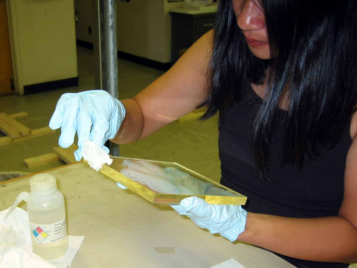 |
All pieces need thorough cleaning before assembly. |
 |
The small support blocks are glued with epoxy to the light guide with smoothed ends aligned for attachment to the photomultiplier tube. Care is taken to avoid getting glue on transmitting ends of blocks. |
| The mixed optical cement (Stycast 1266) is cycled through an evacuated chamber to remove gas bubbles that could deflect light transmission. | 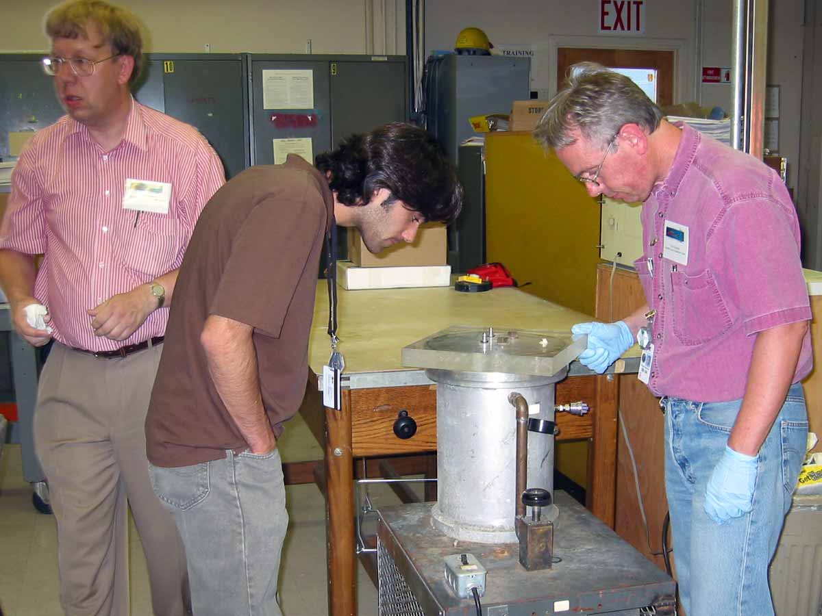 |
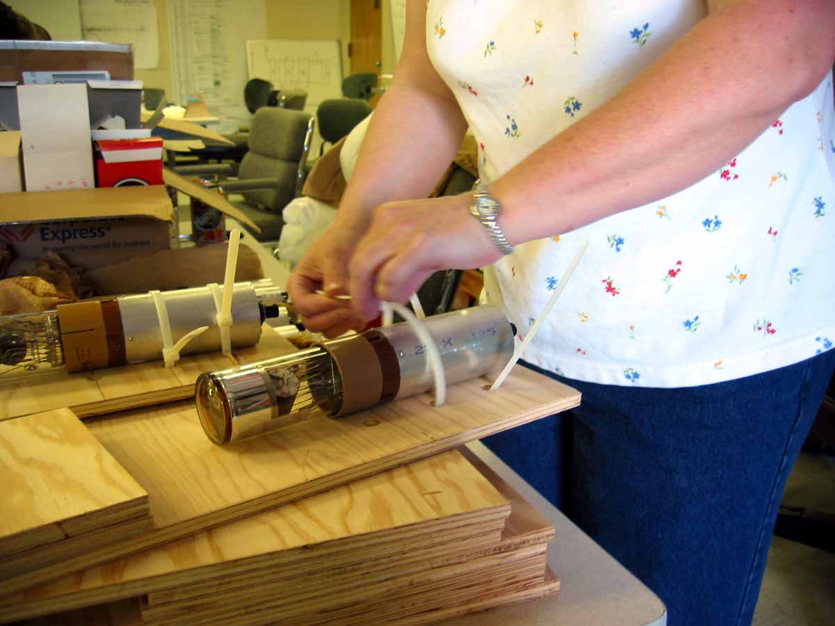 |
The photomultiplier is strapped securely to the support plywood. |
| The light guide is attached to the photomultiplier tube with epoxy glue making sure there are no bubbles to impede light transmission. | 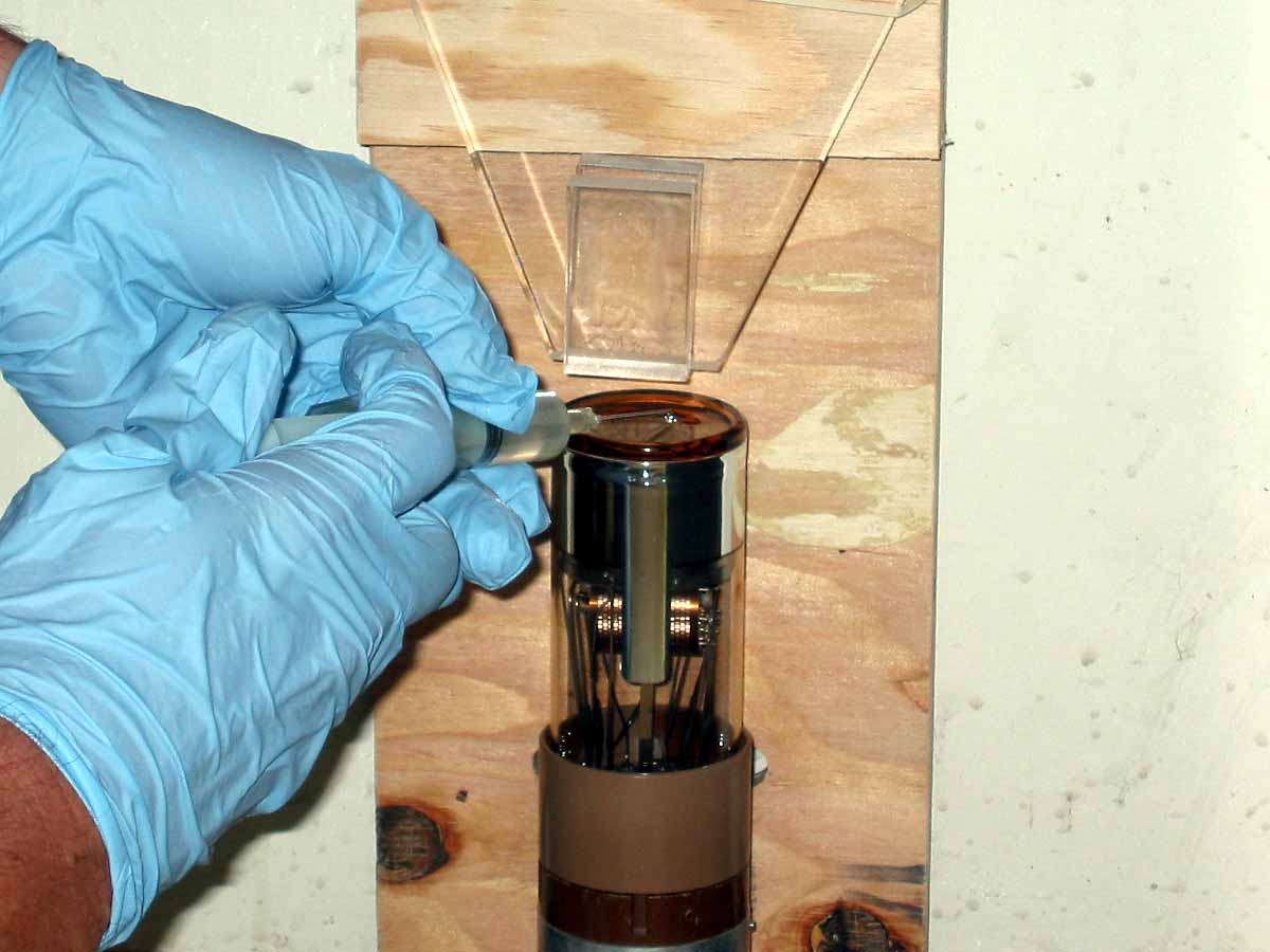 |
 |
The scintillator is then glued and carefully aligned with the light guide. The assembly is oriented vertically and held with rubber bands until the glue sets. |
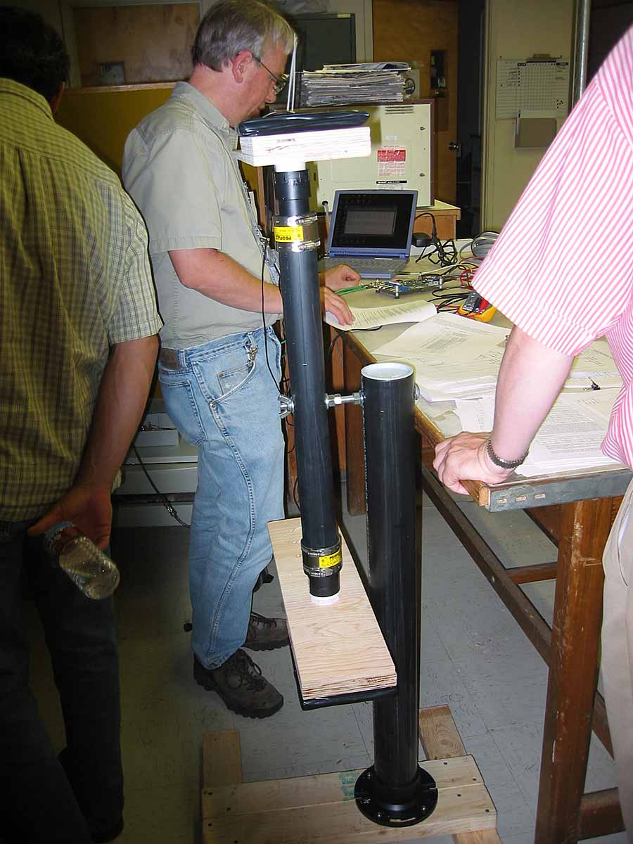
| The support bases are screwed together and the water closet flange attached. |  |
 |
The threaded pipe connections are glued to the smaller diameter pipe. |
| The smaller diameter pipe is inserted into larger plastic pipe and held in position by pipe clamps. |  |
| This movable arm is attached by long bolts, nuts, washers, lock washers, and wing nuts to the large support pipe. The whole pipe assembly is placed in the pipe flange but not glued allowing for disassembly, transportation, and storage. | 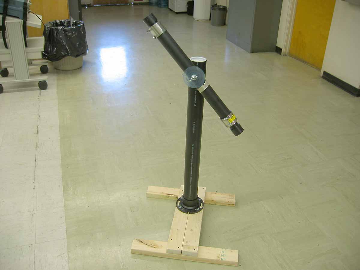 |
 |
The center of gravity of each plywood mount holding the muon detector is located, mounting holes drilled and pipe ends attached by machine bolts. |
| Meanwhile each glued scintillator and light guide is again cleaned. | 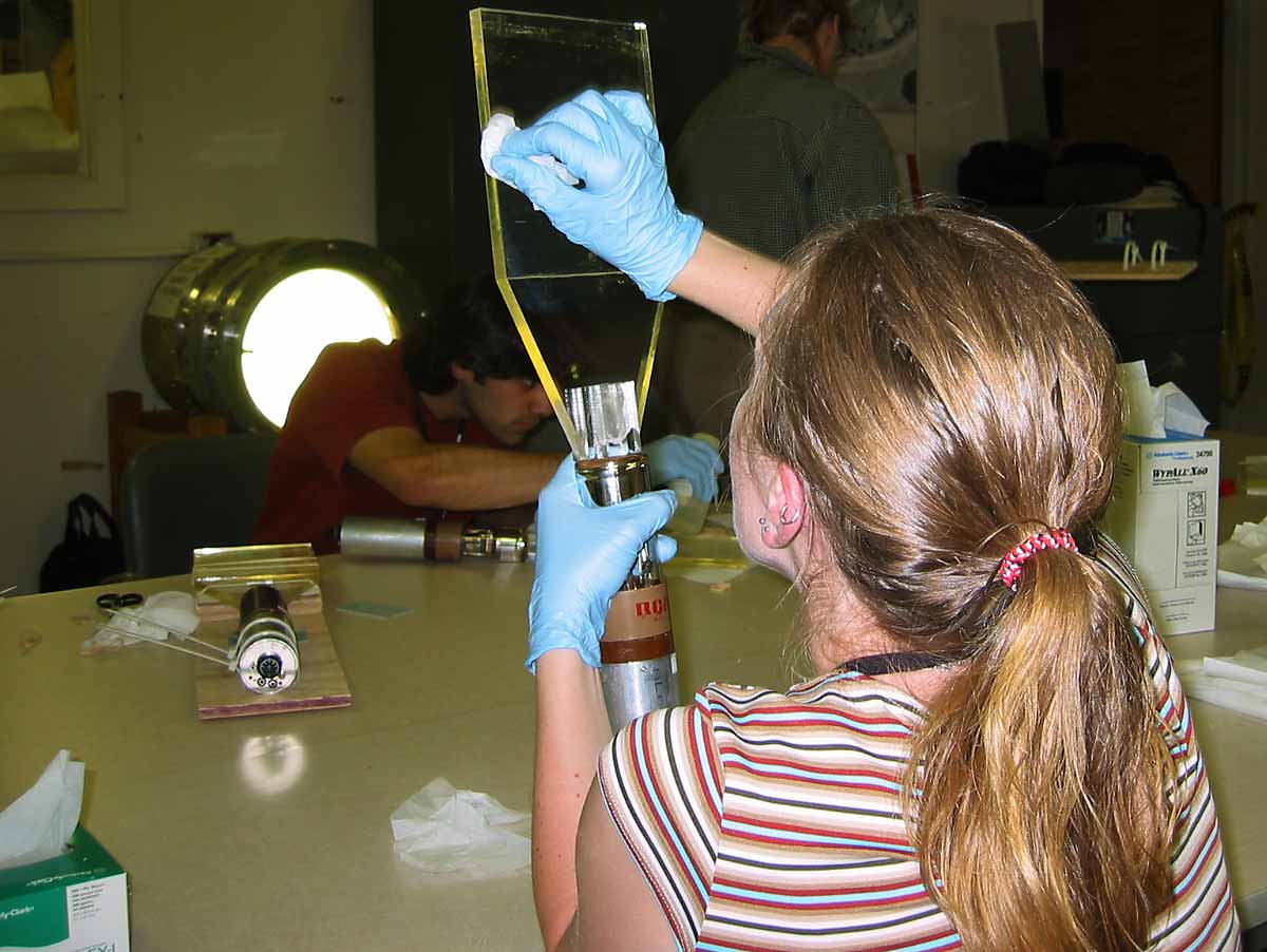 |
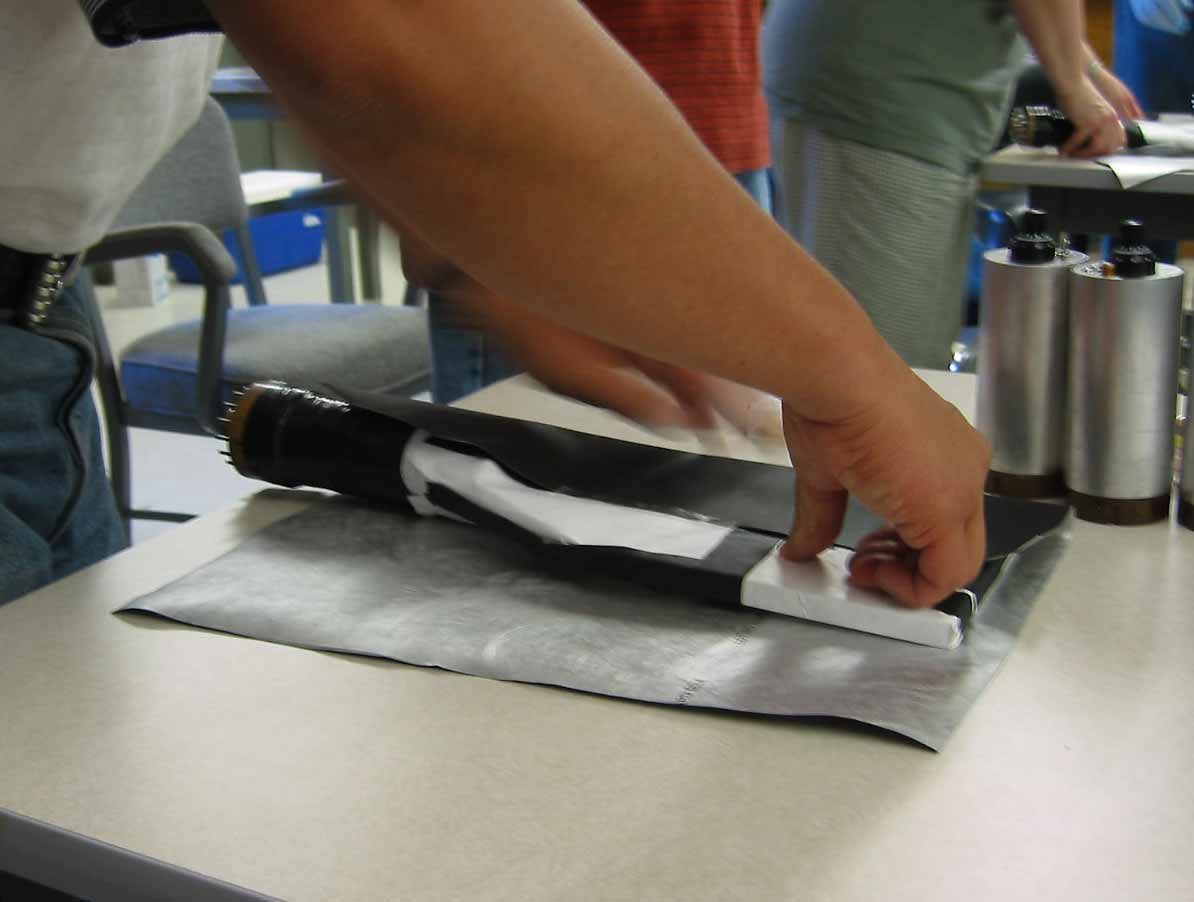 |
The light sensitive apparatus is first tightly wrapped in white Tyvek to reflect any escaping light back into the apparatus. Marvelguard is then folded around the apparatus with silver side inward and black side outward to block any room light. |
| The cosmic ray detectors and photomultiplier tubes are wrapped with several layers of black tape to further block entry of any room light. | 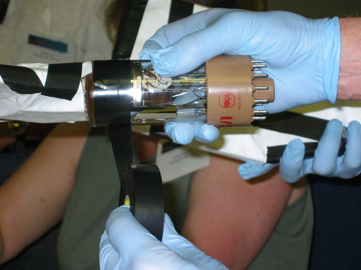 |
| Seven completed detectors: each scintillator, light guide, and photomultiplier tube is fully wrapped. | 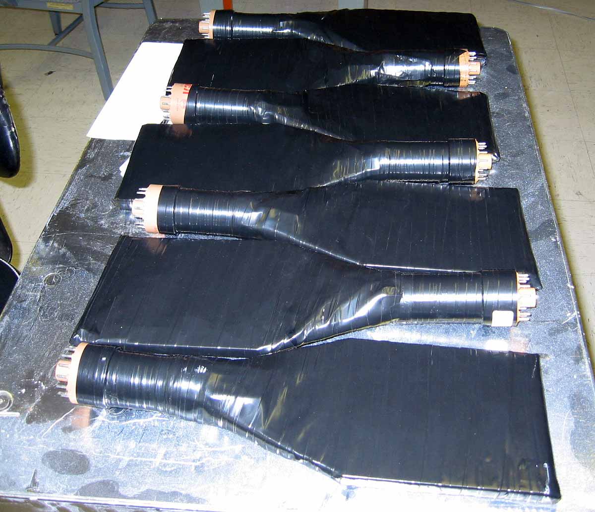 |
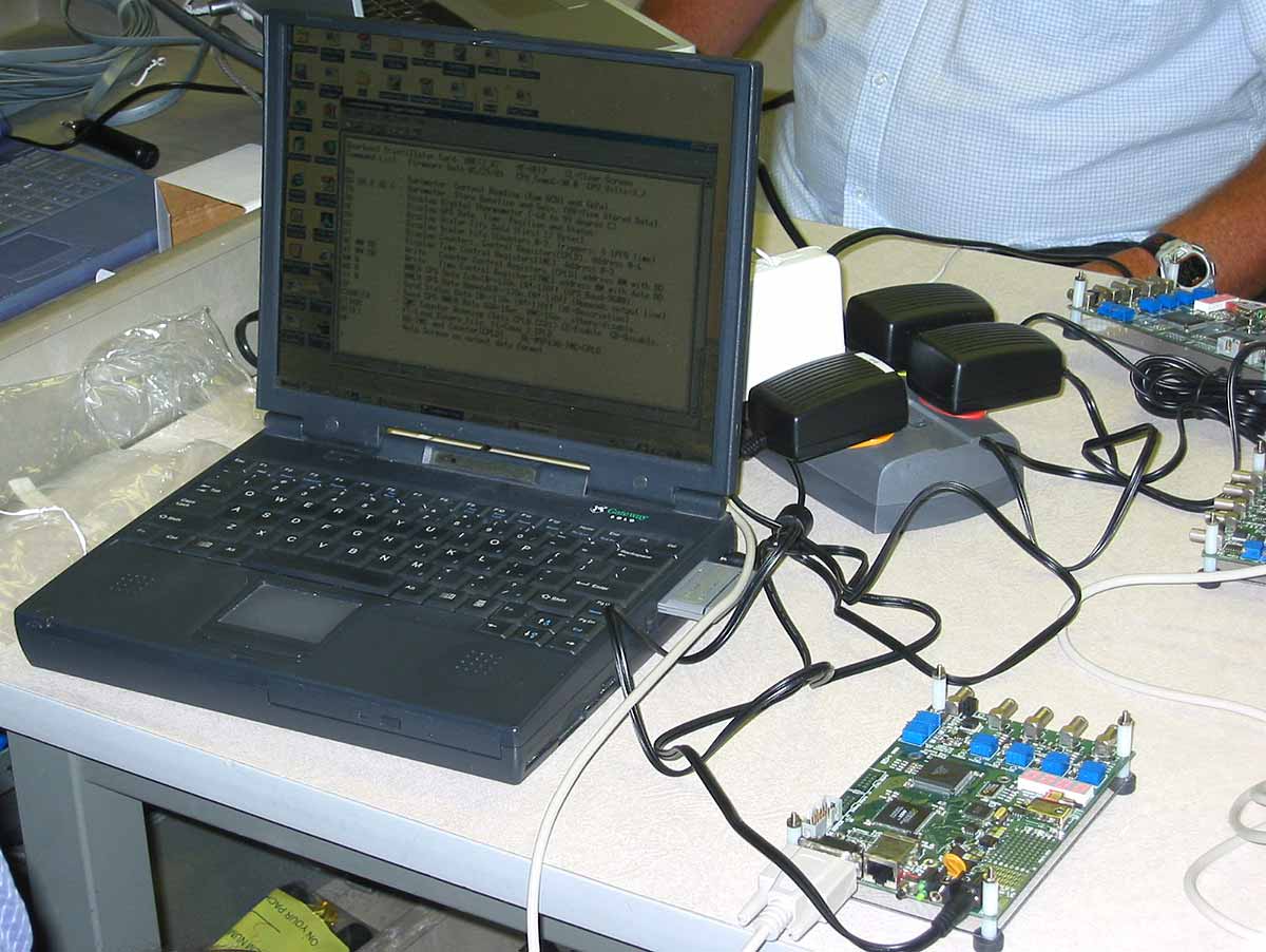 |
Each circuit board is checked to determine if it responds correctly to input signals. |
| A special photomultiplier base amplifies 5 Volts to a variable high voltage. Each adjustment Helipot is calibrated by measuring the output voltage for a variety of settings. |  |
| Inside of a photomultiplier base. | 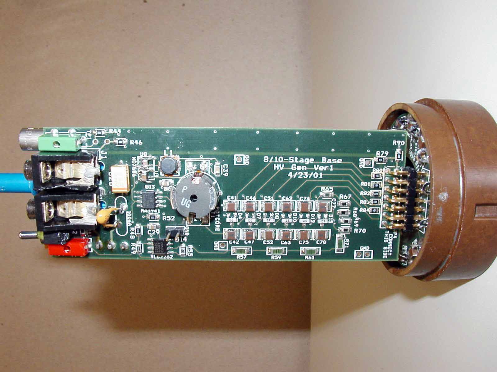 |
 |
|
| Since 2003, FermiLab has continued to improve the design, performance and reliability of the cosmic ray detector. It is now batched produced, distributed in kit form to QuarkNet teachers around the United States, and sold at cost to educational institutions around the workd. At right is the 2009 four scintillator QuarkNet detector, circuit board, GPS unit and wiring (excluding 5V power supply) | 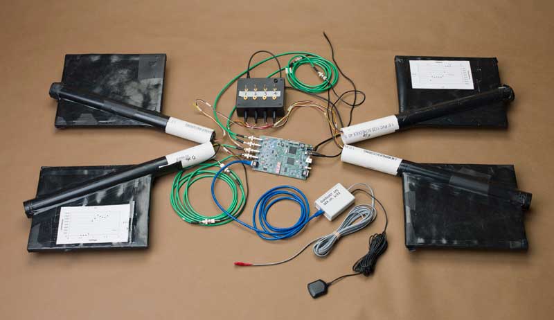 |
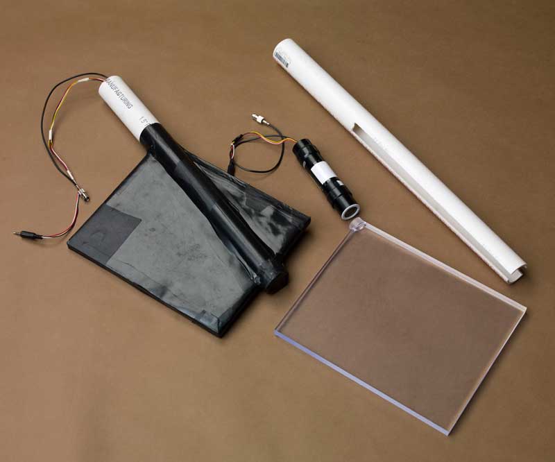 |
2009 QuarkNet scintillator paddle, beside unassembled parts. Note the simplicity, reduced photomultiplier size, and minimal joints which could be damaged. |
The Cosmic Ray Detector construction portion of the 2003 SLAC QuarkNet Teacher's Workshop involved a significant amount of behind-the-scenes "volunteer" work by a number of people. Tom Glanzman and Willy Langeveld, co-conveners for this portion of the workshop, would like to thank the following people for their generous and important contributions:
- Tom and Willy
Thanks to Dave Hoppert of QuarkNet at FermiLab for the photographs of the 2009 detector and parts.
![]()
to SLAC QuarkNet page
to Cosmic Ray e-lab (QuarkNet at FermiLab)
to SequimScience main menu